The Mutianyu Great Wall: Or, a fundamental misunderstanding of stairs

Having finally gotten actual, predesignated time off, I decided to spend New Year’s in Beijing. So, I bought my ticket, and booked a few nights in an almost suspiciously cheap hostel for its location. I like hostels because the people there either know their stuff or you can learn from their mistakes.

Anyway, having known that most hostels and hotels offer tours at the front desk, I decided to get a ticket for one of the wall tours, as one does not simply go to China and not see the wall. Of the three tour options, I decided on the Mutianyu wall section because it was:

  1. Cheapest
  2. Boasted access to the unrestored wall
  3. Had a luge*

Continue reading

The Research Centre of Nanchang Porcelain Painting: Or, even the statuary is unhappy

I have the unenviable work schedule of not having consecutive days off*. So, instead of travelling far and wide, absorbing the local culture and history, I have to stay in the city and absorb culture here. (Hint: it’s mostly drinking.) To this end, and to the end of not spending my time vomiting baijiu into a squat toilet**, Google and I have gotten very friendly while looking for things to do.

Enter eChinaCities, where the Nuo Culture Park is listed as 2nd of all the possible attractions in Nanchang! It has everything – a park, vendors, performances, two museums! Unfortunately, the bus directions are… less than helpful, and I couldn’t get the map to work.

After an abundance of online sleuthing, wherein almost no one mentions the “Nuo Culture Park” beyond saying that they started charging at the gate, and a book on Amazon to verify its existence, I found “Nanchang China Nuoyuan”. To get there, you need to take the metro line 2 to Wolong station, exit to street level through gate 3, then walk North for about 5 minutes. You can’t miss it, they’ve built a fake grotto.

Continue reading

Finding Your Sensor Width: Or, it’s like Hansel and Gretel except the breadcrumbs are factory specifications 

(…and the gingerbread house is made of more work!)

I haven’t mentioned this before, but I like to use my cellphone camera for photogrammetry, instead of my dSLR. I have my reasons; good reasons, even. It does, however, create a fairly significant hurdle – sensor size.

Because of reasons my uneducated meat-brain has yet to grasp (I will figure it out. One day, just you watch!), the physical size of your camera sensor plays into the triangulation algorithm. Now, if you own an actual, designated camera, or one of the more popular cellphone models, you should be fine. Most of the Open Source photogrammetry programs* rely on this database for the camera metrics.

My phone (a Moto E2) was not in that database when I started. Some light blasphemy might have accompanied that realization. In the interest of Pretending-to-be-Productive-Today, I went out to find what I thought would be a fairly evident bit of information.

As is a frequent occurrence in my life, I was wrong. Let’s watch!

Step 1: Find Your Camera’s Sensor Model

I am firm in my belief that Google holds the answer to all society’s mysteries, if only one is canny enough, brave enough, and [un]lucky enough to find them. So I typed “Moto E camera sensor size” and began my search. After going through a few sites and concluding that no tech blogger actually cares about anything other than megapixels, I found this site. Tom helpfully told me that I had a 1/5″ CMOS sensor.

I did a quick conversion and got 5.8mm. Success!

It took me a bit to remember that that was the diagonal measurement, not the width, and I couldn’t just type that in and call it hunky-dory**.

Step 2: Check the Size Against a Table of Information

Okay, Google got me part of the way, I know what kind of sensor I have. I’ll ask Wikipedia about sensors – and look! They have a chart! Everything’s better with charts!

Sadly, it was a chart without 1/5″ on it.

It did, however, have a bunch of other measurements, so your search might yet be over. If not…

Step 3: Find Manufacturer or Vendor Specifications

Back to Tom. The sensor is actually a Samsung S5K5E2 1/5″ CMOS, so I Googled that and got the factory specs from here. No measurements here, either, but I did learn a new thing – Optical Format (OV).

Apparently, that 1/5″? Not actually 1/5″. It’s not even rounding to a tidier number, it’s just a lie. A physics based lie. A lie with math. The most insidious lie of all. But we’ll get back to that.

Okay, now I’m just gonna search “1/5″ CMOS sensor”, like I probably should have done twenty minutes ago.

And look: first hit – 2.8×2.1mm. But wait, what’s this? “Miniature CCD/CMOS lens for 1/5″ or smaller format imager”.

A quick Google image search and the entire thing becomes clear.

1-5-cmos-sensor-infinity-look-small
Notice anything?

The sensor isn’t a sensor. It’s a sensor plus optics.

That OF? The effective size of the sensor when distortion from the lens is taken into account. Because the lens is a little bit wide-angle, it “squeezes” the light in at the edge of the frame, so a bit more hits the sensor and makes a picture that little bit more inclusive of reality.

Physics based lies.

Step 5: Add It to the Database

Be a good Samaritan, don’t make anyone else go through this, just make a GitHub account and modify the document as follows:

Camera make;model;sensor width

For me, that was Motorola;MotoE2(4G-LTE);2.8

sensor data

Alternatively, if you’re feeling less generous, or you don’t want to wait for your edit to be merged, open up your copy of “camera_database.csv” with a text editor that supports UNIX formating. I use Notepad++, but so long as the program has a column with the line numbers listed on the left you should be golden. Just type in the same make;model;sensor width and save. Make sure to restart your program for the changes to take effect.

…And that’s it. Go forth and photogram!***


*By “most” I mean “three of the four or five I’ve actually tried beyond reading their ‘about us’ page”

**Excuse me, I have some files to modify

***I raise the motion to make “photogram” a verb. Seconded?

Step 4 Scultpting and Printing: Or, In Which Making a Hole is Much Harder Than Can Be Reasonably Expected

Following my last post on basic meshing, the amphoriskos was left as a solid Lump of Thing. Not ideal digital display purposes, and certainly not for printing (the current be-all-end-all of digitization). So, how does one make a jug more jug-like? I’ll show you how. I’ll be starting with this:

… and working from there. File’s up for download iffn you want to follow along. The first thing you need to do is download and open Meshmixer (link) (henceforth MM, as I am lazy and don’t want to keep typing “Meshmixer”).

Alignment and Scaling

Skipping ahead to the point where you’ve opened your object in MM, you’ll notice that the orientation is probably off-kilter of center. To fix it, you’ll need to go to Edit>Transform. You’ll be faced with a window where you can imput values and an xyz-axis like the one below.

scaling-and-such

Wobble it around until you’ve got it however you think is right-side-up. Heads up, this could take a while. Once you’re there, click Accept, then go to Edit>Align; if all is well, there should be another window and a bright 3-axes symbol with the y-axis going straight up. Click accept again, and go back to the transform tab. Now comes the fun bit – scaling. I know that the Amphoriskos is about 10cm (100mm) high, and can change the y-scale accordingly with the auto-scaling doing the rest of the work. Because mine initially registered as being fractions of a millimeter large, there was some glitchiness when I expanded it 100-ish times. The glitches were superficial, but if you get them and they bother you, save the file and re-open it; that should clear it up.

You’re now done with setup and can do the real work.

Solidifying and Hollowing

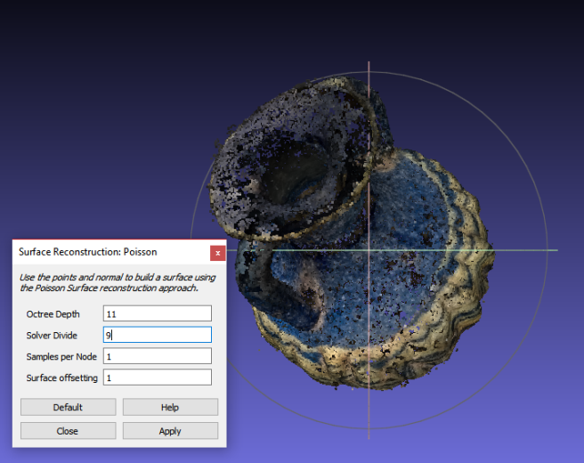
Now, for reasons I can only assume are because MM and Meshlab aren’t 100% compatible*, STL files don’t register as being properly solid and can’t be hollowed out. This is easily fixed by going to Edit>Make Solid and imputing the best values – I just maxed out the quality and let nature take its course.

solid

With my newly solid block, I went to Edit>Hollow and changed Offset distance to 3.25mm, because that seemed right-ish. FYI, printers have a minimum “safe” threshold for borders – generally about 2mm – otherwise they’re in danger of collapsing. Consider that before making the walls thinner than 2mm. To check that the hollowing worked, I Edit>Slice’d my object then Ctrl+Z’d it back to wholeness when I was done.

Opening the Neck

This bit, this bit here, was the most frustrating bit. I went through 5 pieces of software trying to get it right, then went back to MM because it ended up being easiest**. I’m still not entirely happy with it, but it works, so whatever.

Looking back at the hollow half-piece above, you can see that there’s a 3.25mm piece covering the mouth of the neck*** – I wanted that gone. Because jar.

So, what I did was go to Meshmix>Primitives and drag-and-dropped a sphere into the neck hole. After scaling the sphere to roughly neck-hole size, I selected Boolean Subtract from the menu and clicked accept. After it had run, I was left with this:

Not super tidy, and not physically accurate, but pretty good for someone who can’t redo the photos. Almost done!

Sculpting

So, for the last bit of proper work, I smoothed everything out into a close approximation of correctness.

sculpting

That ended up being:

  • Flattening out the divots where that stand had been
  • Closing up the hole on the lip
  • Filling in and flattening out the irregularities inside the neck

Since I didn’t want the inside of the neck to be too uniform anyway, I had a pretty loose hand with the tools. I ended up having to export it as an STL file and open in it up in Meshlab a couple of times to check for problems, but it all worked out in the end. This bit’s all pretty intuitive, so just fiddle around with it.

Save and export as an STL file.

You are now ready for printing!

Note: Immediately after finishing this post, Meshmixer just. Stopped. Despite my best efforts, and multiple re-installs across multiple computers, it is still too fritzed to use. Because of that and the fact that I made a mistake while editing, there’s no Sketchfab window yet.

Note 2 (April 4, 2017): Problem resolved. It turned out that my model was too small – 10cm high. I guess the first time I left the scaling for last, but started with it pretty much immediately on subsequent edits. Scaling up let normal function resume, and the issue was logged for future updates.


*Probably wrong

**123D + Sculpt: Can’t import files to edit.

TinkerCAD: Can import STL files, but the file exceeded the max number of triangles.

123D Design: Can import files, file didn’t exceed parameters, laptop didn’t have enough power to run it properly.

Blender: Probably does everything anyone could ever want and washes your car, too, but the learning curve is insane. Waaaaayyyyy more work than a hole warrents.

Meshlab: Not made for this, bad things happened. Just no.

123D Design also had some terms of use that I didn’t agree with (Autodesk has the right to use any creations for advertising-type purposes; and it looked like there was some stuff about commerial use [i.e. freeware=you can’t profit from stuff you make], but I didn’t read too much into that).

*** That… doesn’t sound right…

† Speaking from personal experience, you want the supports. Forgetting them will probably result in either a collapsed model or having to MacGyver a fix while trying to not get burned by molten plastic.

STEP 3 Meshing: Or, the Janitorial Work of Photogrammetry

So, you’ve finally managed to get a usable point cloud out of whatever piece of photogrammetry software you use – Go you! I’m sure it was a long and arduous journey, the likes of which deserves a ballade to honour you perseverance*. Unfortunately, that point cloud is pretty useless. I mean, it’s really just a cloud of points, it’s right there in the name. The glory that is meshing will fix that for you. Meshlab is pretty heavily recommended program, and I hate to break a trend, so I’ll be using that. Onwards to the rapid-result tutorial!

Step 1, Cleaning your Point Cloud

For this workflow, I’ll be using a 5-6th century BCE mediterranean Amphoriskos from the University of Saskatchewan’s Museum of Antiquities. As someone who knows next-to-nothing about glass work, it’s a gorgeous piece of work combining yellow and blue glass with added handles. It is, however, built a bit like a glass bludgeon in its heaviness. You can also download the raw point cloud file on Sketchfab, if you want to follow along.

Upon opening your point cloud, you should get something like the mess pictured above. All noisy and full of spots and things. Simply dreadful. My favourite ways of deleting those spots are to either manually select them, then delete them, or to select by colour (Filters>Selection>Select Faces by Color) then delete them. It’s pretty straight forward.

point-select
Pro-level editing skills not required

Step 2, Meshing

Once you’ve got something looking like this, more or less clean with only a few bits right near the surface, you’re going to want to mesh this. To do that, go to Filters> Remeshing, Simplification and Construction> Surface Reconstruction: Poisson and you’ll get this box

poisson-reconstruction

Change the values to Octee depth:11 and Solver Divide:9, or something else if you’re willing to risk a program crash. If all goes well, you should get something like this:

Step 3, Colour Transfer

Now, as nice as your featureless, grey object is, some colour would probably be nice. To be that, go Filters>Sampling>Vertex Attribute Transfer and change the switch the source and target meshes so that your “poisson” mesh is the target, and your point cloud is the source.

attribute-transfer

Once you’ve applied the settings you should get coloured mesh that can survive without its parasitic point cloud. To save, File>Export Mesh As…>File_name.off. And you’re done, bask in the glory of your accomplishment!

As you can see, there are some problems with my final product – the neck is insufficiently neck-like, and the whole thing is one block of object (poorly) digitally painted to look like a ungentarium**, but you get the idea.

For further instruction from someone who actually knows what they’re doing, I suggest Mister P‘s youtube tutorials.

Trouble Shooting in Meshlab:

I’ve made a horrible mistake, how do I fix it?
You’re alone and your life is falling apart. “Ctrl Z,” you say, “Ctrl Z”. Nothing happens. It cannot be undone; as it is in life, so it is in Meshlab. Start over.

I did the “vertex attribute transfer” thing exactly like you said, but the colour won’t transfer from my points to my mesh.
No problem, I’ve only gotten it to work for me, like, four times. Total. Ever. What you want to do, after transferring the attributes, is to go to Filters>Color Creation and Processing>UnSharp Mask Color, and click apply. The default settings work fine, but you’re welcome to fiddle bit. And voilà, colour!

The colour still isn’t transferring. Why are you lying?!
Are you absolutely certain you used your point cloud as the source and your poisson mesh as the target? Because it’s not the default setting.

Nothing saves right. My mesh saves as uncoloured points and my points only open in VLC and I think witchcraft was somehow involved.
Okay, for a start, make a copy of your original, just in case. Now, when you’ve finished editing a step, save like this:
(For point clouds) File>Export Mesh as…>Export as .ply
(For meshes) File>Export Mesh as…>Export as .off
There’s probably a more logical way, or a way which saves both mesh and vertices concurrently, but this is the easiest one I’ve found.


*read: irrational stubbornness

** ungentarium. Best word.


Why You Shouldn’t Zoom: Or, A lesson from Alfred Hitchcock

https://i0.wp.com/i.imgur.com/EUwXKvf.gif

That is the Vertigo Effect, or Dolly zoom – Alfred Hitchcock used it in his film Vertigo,  to visually portray that nauseated sinking feeling in your stomach when you come to an unfortunate realization. You know the one*. It’s also the perfect illustration of why you don’t zoom in or out while you’re in the middle of a photogrammetry shoot.

How it works is that the camera operator moves closer to the subject while zooming out with the lens. And vice versa, out-in. As you can see, that causes some spectacular distortion, most visibly in the background. But just because the soon-to-be shark lunch looks the same throughout, doesn’t mean he is. While the centre of image is less subject to change, the triangulation is very reliant on exact values and – unless your camera is much better than mine**- your camera only notes one focal length per lens and makes no note of whether that changes.

So, that’s a whole set of features post-zoom that are completely different from the others pre-zoom. How does your computer account for this? Best I can tell, it doesn’t. Your computer has a crisis of intelligence and discards it all. Then it takes the time to gives you null results, just to rub it in.

Other programs, not PPT, seem to do fine with mixed focal lengths. Still, it’s a bad habit and makes everything that much harder for your computer.

In brief, suck it up and just lean in to get the shot. Parallax’ll do it some good.


*That shot’s from JAWS, if anyone is in the mood for ridiculous exploding fish.
**it probably is

Cellphone Lenses: Or, Look – you finally have a use for them!

So, I’ve been having trouble getting a set of points to render (points as in lithics, to clarify)- not enough detail, I suppose. I don’t have a macro lens, but what about a cellphone lens? Now, knowing that an additional lens will mess up the pre-programed focal length, I don’t have high hopes. But I’ve also been wrong on every assumption leading up to this point, so why not?

So I went out and bought the most high end phonography lens kit I could find!

image

$5. That cost $5. Actual glass optics and everything. Really broke the bank.

Here’s the quality of image the macro got:
image

image

Surprisingly good, but a really shallow depth of field*. There’s about 121 of those, but plenty are blurry or almost identical. Also, the lazy Susan was to big to use, so the whole thing was rather painful.

After PPT scaled to 0.5 was done with it, I got this:
image

Only one side, again, and an absurd number of artifacts, but the texturing of the mesh underneath is pretty good. All the same, not ideal. I think the ID tag is anchoring the whole thing, to be honest.

Tried again without scaling:

https://skfb.ly/MYCN

For some reason only the opposite face worked, and I’m kind of baffled by that, but whatever, not actually the first time.

Hesitant partial success?

*That’s The Road to El Dorado playing in the background, if anyone cares.

The Evils of Interior Design: Or, How I learned to hate every archaeologist to ever scrub paint off of a statue

This is Apollo Lykeios -because he has a lyre, you see?- and he was the first thing I took pictures of to run through Python Photogrammetry Toolbox (PPT). There were 215 photos, total. From the tips of his toes, to the draping under his hand, to the curls in his hair, I had it all.

So, I’m all set to go. I open PPT, load all 215 photos, check the camera database…path fail. Okay, that’s fine, I can fix that*. Bing bang boom, time to try again.

“Camera in database”.

Sweet. Now to set the size (0.5) and run the feature extraction. Hours later, and after thinking I’d crashed it, I got my .ply file and opened it in Meshlab.

The result? A few scattered points that, when meshed, looked a bit like a turd**. Not a paragon of superhuman beauty.

Okay, try again with 10 photos.

Camera in database. Scale to 0.5. Features identifying. Blah, blah, blah.

Aaannndddd a 1KB .ply file that when opened was entirely empty. Not even a turd-mesh.

I ran it few more times with slight variations. Always the same, empty file. Apollo became my enemy***, because if you’re gonna hate a god you might as well hate one that brings light and music to the world.

ATOR (the makers of PPT) had a comment section on their tutorial where a few people had the same problem. The response was to check that they were extra super sure that they’d checked if their camera was in the database. I emailed them for advice. They never responded.

So, not having found anything actually useful, I uninstalled all three of the associated programs and installed them again from scratch. Then I ran the 10 photos again. You know, just in case.

1KB .ply. However, amidst my cursing of my computer, its ancestors, and its cow, I saw a line of code at the bottom of the python dialogue box. It read:

Total pass fail0 fail1 refinepatch: 0 0 0 0 0

Total pass fail0 fail1 refinepatch: -1.#IND -1.#IND -1.#IND -1.#IND -1.#IND

Figuring that meant my photos were the problem, I went out and re-shot it. The Canon photos turned out the same as the initial batch, but my cellphone got a pretty good partial reconstruction.

image
The blurry face of beauty.

It didn’t have a back or anything, but a result is a result. However, looking back at the photos I realized something – there were three shots where Apollo was cast strongly in yellow, while the rest had auto-corrected the exposure. My Rebel had done the same exposure correction.

The exposure of a marble replica in a room painted cream.

A room. Painted. Cream.

I’ll let that sink in for a sec.

So, best guess? The lack of colour variation in both the room and the statue itself meant all the features were coming up as too similar to match and the program just said “screw it” and gave up. It’s a problem I’ve yet to resolve.


* with help
** I still haven’t figured out why that happened. Best guess is that the 215 photos had a couple of false matches across them.
*** #HeliosForSunGod